OSPF (Open Shortest Path First) is a routing protocol developed by Internet Engineering Task Force (IETF). OSPF is standards-based which means it is available on routers by Cisco as well as other vendors, making it a vendor-neutral routing protocol. This is in contrast to Enhanced Interior Gateway Protocol (EIGRP) that is Cisco proprietary, and hence available only on Cisco routers.
OSPF divides its routing domain into smaller sub-divisions called areas. These OSPF areas are numbered and each may have several OSPF routers in it. OSPF area 0 is at the center of an OSPF domain and all other areas are connected to it. It is basically a star topology of OSPF areas, area 0 being at the center of the star. The advantage of OSPF areas is that most of the routing information is contained within an area and only summarized routing information is sent to routers in other areas. This makes OSPF very efficient in terms of usage of resources like processing power, memory, and bandwidth. The conservative resource usage in turn enables OSPF to scale well to very large typologies.
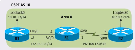
Let’s start configuring our simple OSPF topology with a single area 0 in autonomous system (AS) 10 as shown in Figure 1. We will not go into the details of IP address configuration and assume that all IP addresses have been pre-configured on all interfaces including the Loopback interfaces as shown in the figure.
Figure 1 Configuring OSPF
The router ospf command entered in global configuration mode with autonomous-system-number argument creates an OSPF routing instance. It is the first step in configuring OSPF on a router as done here on R1:
As you may have noticed, we moved from global configuration mode to router configuration mode as indicated by changed router prompt.
The next step in configuring OSPF is to specify which router interfaces are included in OSPF using the networkcommand, also mentioning OSPF area the interface belongs to. The router would send OSPF messages and try to establish adjacencies with other OSPF speaking routers off these interfaces. We will enable OSPF on Fa0/0 and S0/0 on R1, placing both interfaces in area 0:
And that completes our OSPF configuration on R1. We would proceed with configuring OSPF on R2 and R3 following the same pattern, also enabling OSPF on Loopback0 interfaces:
That completes our OSPF configuration on R1, R2, and R3 and its time to verify if our configuration works as expected. If we configured OSPF correctly R1 should have established OSPF adjacencies with both R2 and R3. Let’s see if that’s the case:
You can see two neighbors 10.10.2.2 and 10.10.3.3 which happen to be Loopback0 IP addresses of R2 and R3 respectively. More precisely, 10.10.2.2 and 10.10.3.3 are router IDs of R2 and R3 respectively, as an OSPF router chooses the highest IP address on a Loopback interface as its OSPF router ID by default. The output shows R1 has successfully established adjacencies with both R2 and R3. We can probably hope that some routing information exchange may also have taken place by now, populating the routing table with some routes.
R2 knows about 10.10.3.3/32 network, and observant readers may have noticed the /32 mask. Please refer to Figure 1 and note that we configured our Loopback0 interfaces with /24 mask. This apparent anomaly is the default behavior of OSPF, advertising Loopback interfaces with /32 masks. Let’s now seal the deal by pinging Loopback0 of R3 from R2 confirming end-to-end connectivity.
When you implement this topology in a lab, you should use the show commands seen in this article on all your routers, closely examining the output. This would be fun and a great way to get to know OSPF better.

No comments:
Post a Comment